| Battery chargers (conductive & inductive) |
|
Conductive type
An example of a conductive charger adopting a single stage circuit is described here. An active filter for power factor correction and an inverter generating high frequency alternating current are integrated into this single stage circuit.
A 2-stage circuit configuration, which used to be a main stream, is shown in Fig. 1. When commercial power source is converted into direct current, power factor correction is performed by an active filter. Then, this direct current is converted into high frequency alternating current by the inverter, and then rectified again and charged to the battery. This circuit configuration has two switching circuits in series, so the configuration is complicated and expensive. Therefore, there was a limit to how much downsizing, weight reduction and increase in efficiency could be accomplished.
An example of a single stage circuit is shown in Fig. 2. Commercial power source is converted into direct current, and power factor correction and conversion into high frequency alternating current are performed in parallel by a single inverter. Thus, only one switching circuit is required, which facilitates lowering cost, downsizing, and weight reduction. Additionally, highly efficient approach can be expected because switching loss is less than that of 2-stage method.
Inductive type
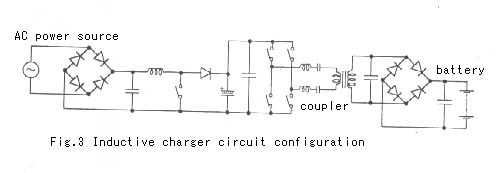
An example of the inductive charger circuit configuration is shown in Fig. 3. Different from the conductive charger explained above, a 2-stage circuit configuration is employed. As shown in the Fig., the functions are divided into two parts. The primary rectifier, active filter, and inverter are external, and the inlet and secondary rectifier are located on-board.


Reference
Book title: EV Handbook
Written by: EV Handbook Publisher's Group
Published by: Maruzen Co., Ltd. (URL http://www.maruzen.co.jp)
|
|