| Switched reluctance motor |
|
Switched reluctance motor
The switched reluctance motor (SR motor) is also called
the variable reluctance motor (VR motor). In 1838, Davidson made
the first model of this type. This motor has neither a permanent
magnet nor a coil in its rotor, so its structure is simple and cheap,
and its mechanism is durable. The lack of a permanent magnet in
the rotor prevents overheating magnetic interference with the transmission;
it can also be driven under high-temperature conditions. However,
the control system must be able to control the current precisely
to drive this motor. they can only drive such as the base of a cannon
common at that time technology level.
In the 1950s, the motor was used as a step action motor, but it
was known for its noise and vibration problems. Through progress
in simulation technology and electronic controls, the design of
the poles and coils was improved, as was the wave shape control
of the drive current. The SR motor has recently become the motor
of choice in mass-produced electric vehicles because of its low
cost and good durability.
Structure and the actuating principle.
The SR motor has pointed poles in both the stator and the rotor.
Each of the coils of the pointed poles in the stator is fed the
actuating current according to the location of the rotor. The
current creates a continuous magnetic pulling force for the rotor
that allows it to rotate.
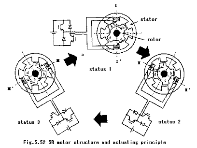
Figure 5.52 shows the structure and the actuating principle. This
figure shows the example of 6 poles in the stator and 4 poles
in the rotor. This is called a 3-phase 6/4 structure. The stator
is made of laminated silicon steel sheets and the coils of all
the opposite poles are connected in series. The rotor is also
made of laminated silicon steel sheets. Figure 5.52 shows the
actuating principle. The current is fed to stator poles I and
I' to induce the magnetic force that pulls the rotor poles a and
c to I to I', respectively. This in turn creates clockwise rotation
torque. Pole a of the rotor comes to the same position as pole
I of the stator (status 2), the reluctance of the magnetic circuit
is minimum, and the pulling force acts in only the radial direction
and does not create more torque. The coils of the stator poles
II and II' are then switched on to feed the current. Pole b of
the rotor is pulled toward pole II' of the stator, and pole d
of the rotor is pulled toward pole II of the stator, thereby causing
the rotor to rotate clockwise. And when pole d comes to the same
position as pole II (status 3), the coils of the stator poles
III and III' are switched on to pull pole a of the rotor to pole
III of the stator to induce a continuous clockwise rotation.


Reference
Book title: EV Handbook
Written by: EV Handbook Publisher's Group
Published by: Maruzen Co., Ltd. (URL http://www.maruzen.co.jp)
|
|